OBC, DC/DC, and inverters of new energy vehicles have all been evolving in the same direction in recent years:The power is getting higher and higher, and the structure is getting more compact.
But after the power is increased, a problem becomes increasingly difficult to avoid -Heat dissipation.
Especially after SiC MOSFETs and SBDs began to be widely used, high energy efficiency, high power density, and temperature resistance up to 175°C have improved performance, but also made heat more concentrated.
As a core power device, MOSFET's heat dissipation capability not only affects efficiency, but is directly related to system reliability and lifespan.
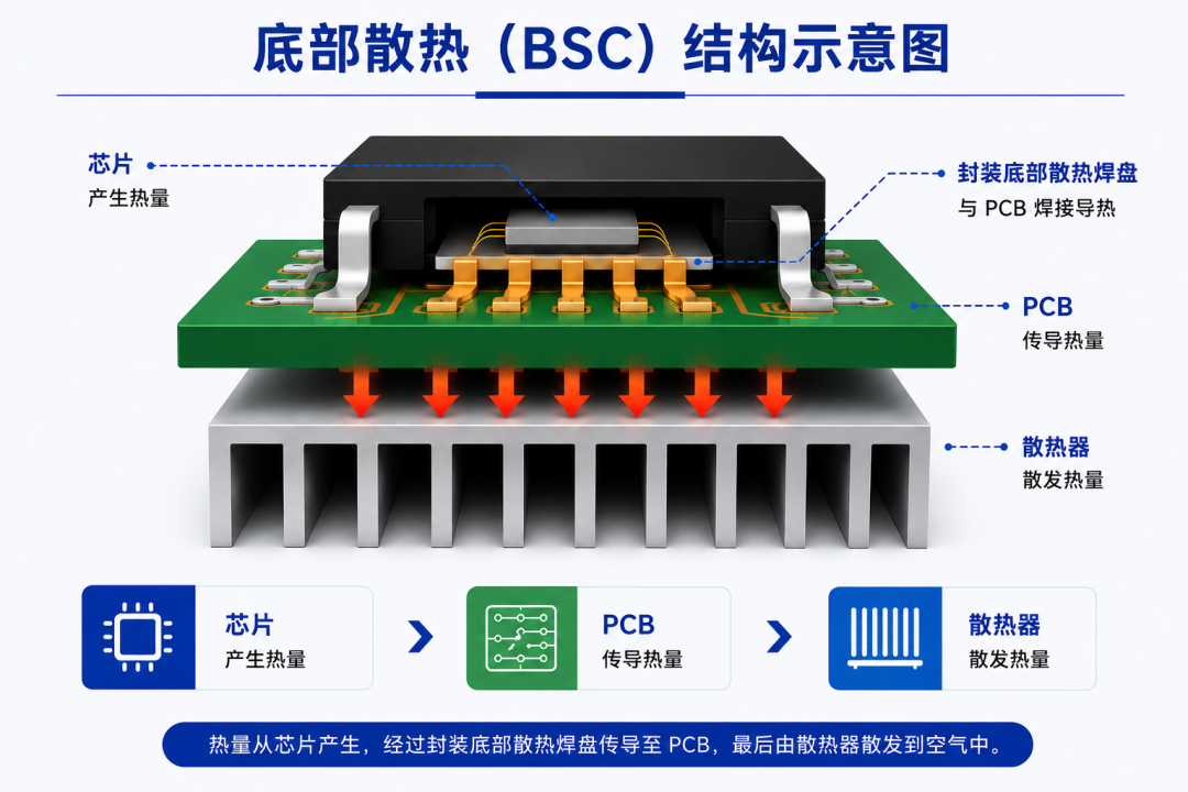
Currently, most mainstream SMD packages (SO8FL, U8FL, LFPAK, etc.) use bottom cooling (BSC). Its heat dissipation path is:
Chip → PCB → Heatsink
In the past, this solution was mature enough, but in today's high power density scenario, the pressure is obviously increasing.
On the one hand, devices are getting smaller and smaller, and on the other hand, the power is getting higher and higher. The extremely small chip area needs to carry a larger load.Heat flux densities often exceed 1000 W/cm² and heat can accumulate rapidly.
To make matters more troubling, this heat must also pass through the PCB before it reaches the heat sink. PCBs, on the other hand, have a thermal conductivity of only 0.3–1.5 W/m·K and are not good at conducting heat themselves.
The heat is piled there, but it doesn't move fast enough, and the junction temperature naturally becomes more and more difficult to control.
At the same time, in order to ensure heat dissipation, space must be reserved under the PCB, and devices cannot be laid out in many areas. For small systems that increasingly emphasize integration, the cost of this space is also getting higher and higher.
In the final analysis, the problem of traditional bottom heat dissipation is actually very straightforward:The heat is not only concentrated, but also "travels too far."
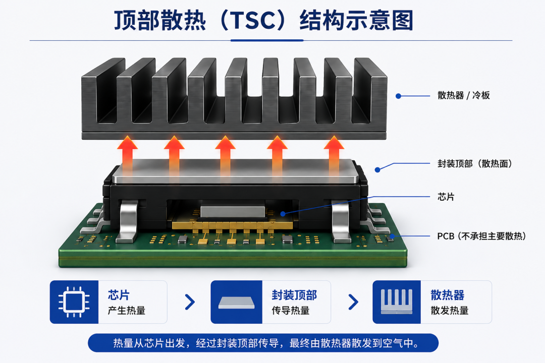
The core idea of Top-Side Cooling (TSC) is not complicated: since the efficiency of downward heat dissipation is limited, let the heat go directly upward. So, the hot path becomes:
Chip → Top of package → Heat sink/cold plate
Without a layer of PCB, the heat conduction efficiency will be significantly improved.
This change brings not only an increase in heat dissipation capacity, but also an improvement in space utilization.
Since the PCB no longer assumes the main heat dissipation function, the space below can be released to achieve a double-sided layout, making the system structure more compact.This is why more and more high-power systems are beginning to adopt TSC structures.
For the same MOSFET chip, reduced thermal resistance often means higher current carrying capacity and greater power output space.
However, after the heat dissipation path is shortened, a new focus also emerges——Interface material between device and heat sink。
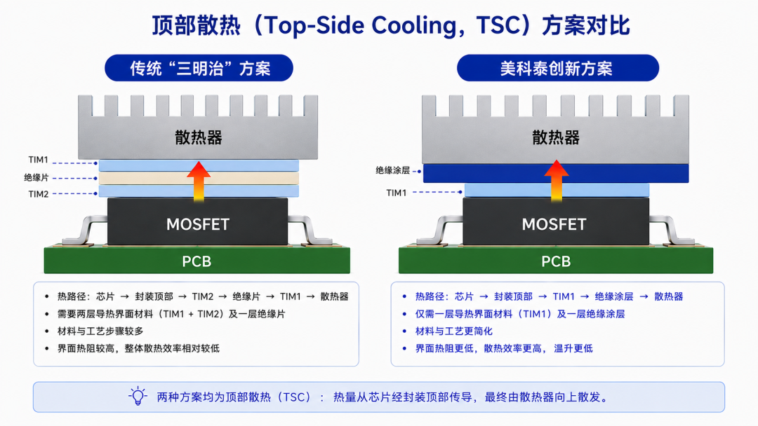
Traditional solutions usually use "TIM + insulation sheet + TIM"Sandwich structure.
This solution is mature and stable, but as the number of layers increases, additional losses will still occur during heat transfer. Moreover, under high-temperature and high-vibration conditions, ceramic insulation sheets are subject to long-term stress and there is a risk of cracking; the assembly process is also relatively complex.
So in recent years, a very obvious direction is:Reduce the interface and shorten the heat transfer path.
The idea of thermally conductive insulating coating is to integrate the three functions of thermal conductivity, insulation and bonding into the same layer of material. Compared with the traditional "sandwich structure", there are fewer interfaces and the thermal path is more continuous.
The changes brought about are also very direct:
Lower thermal resistance
Faster thermal response
Higher structural reliability
For high-power devices, what really affects the heat dissipation efficiency is not the radiator itself, but the heat "stuck" in the middle.
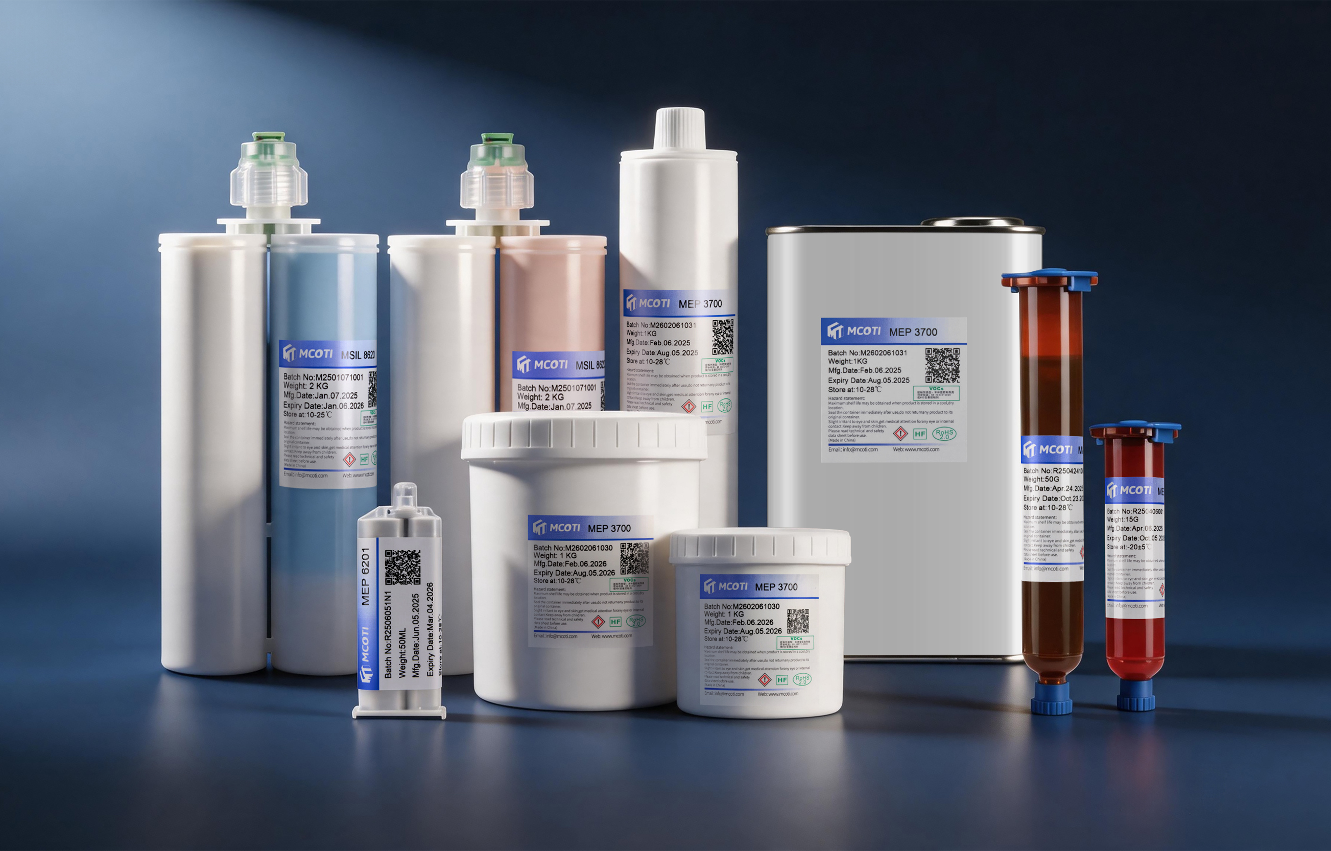
For high-power devices and TSC application scenarios, MCOTI has launched the MEP 3700 series of thermally conductive insulating coatings.
The product thickness is only 100–250 μm, which can meet the voltage resistance requirement of 3000–6000 V, while the thermal resistance is as low as 0.176°C/W.
Using water as solvent is more environmentally friendly
low ionic content
RoHS compliant
High temperature and humidity:
1500+h @ 85°C / 85%RH
temperature shock:
1000+ cycles @ -40~125°C
High temperature aging:
2000h @ 125°C
Under long-term service conditions, the thermal resistance performance remains stable. At the same time, MCOTI's innovative spraying process can achieve a single fine spray of about 5 μm, support complex 3D structure design, product yields can reach more than 98%, and support small batch proofing and verification.
In the past, heat dissipation was more about solving "Can I work?”;
Now it starts to decide"How much more performance can be improved?”。
Top cooling (TSC) allows heat to escape faster, and thermally conductive insulation coating makes heat transfer more stable and efficient.
As power devices continue to develop towards high density and miniaturization, heat dissipation is no longer just an auxiliary design, but a part of system performance.
- END -